About two weeks before all the bike ideas in the last two posts started coming into my head, I had another flash of inspiration regarding the motor system, with the treadmill motor and belt drive, to get a freewheel between the belt and the rearwheel chain, so that pedalling without motor power would not force me to be pedalling against the motor's friction, but still allow the motor to drive the wheel even if I am pedalling, with no intervention on my part.
I checked the inside of the plastic belt-drive pulley the treadmill had used on the end of one of the treadmill main belt rollers, and found that it was almost exactly the same diameter as the Shimano freewheels I have several of, and also a bit narrower in width. Below are two freewheels still on their hubs, one Suntour 6-sprocket to the left, and one Shimano 6-sprocket to the right. Between them is the pulley, and behind them is the treadmill motor. In front of each are the sprockets and spacers that came off of them.
The orange hub still has some other sprockets (off an old Murray) JBWelded on from one of the first failed experiments at motorizing the Columbia with the old scooter motor. They'll have to be removed, as they aren't going to hold up for long with any serious load on them--they'll just shear right off the hub.
I will likely use several of the sprockets here for various things on the CrazyBike, potentially including steering-by-chain (one each of the same tooth-count on steerer and fork tubes), and one each of whatever tooth count is necessary for the receiver sprockets on the transfer axle of the rear frame's last drivetrain segment. Probably I'll use the sprockets that have holes already in them, as that makes it fairly simple to bolt them onto whatever I need to use them for.
If I get bored, I can also take out bike-stealing pirates with them, as ninja sprocket throwing stars. :-P
I considered both of the freewheels before choosing the Shimano, which I picked pretty much solely because it would take very little material removal from the pulley to make it fit, whereas it would have required removing almost all of the inner ring of the pulley to get it on the Suntour freewheel, due to the raised ridges it uses to engage the sprockets' tabs (the Shimano simply uses indentations on the freewheel, and tabs on the sprockets). 
I lathed out about a millimeter from the inside of the pulley, and now it friction-fits perfectly (and tightly) onto one of the freewheels, with all the sprockets removed. Since it's a typical older freewheel, it has the last two small sprockets threaded on, so I used the smallest outer one of those to tighten against the outer face of the pulley, making it even more secure. I don't think I'm going to need to glue or bolt the pulley to the freewheel. It might be necessary eventually to install some bolts thru the pulley, across the lip of the sprocket's chain teeth and the lip of the back of the freewheel, but I may not need to, depending on the torque it will take as it is.
The way this works is the same way the rear wheel would normally work: as the pulley on the freewheel turns clockwise from motor power it will rotate the hub on it's axle, which will also rotate the sprocket that will be bolted to the left end of the hub, which will drive the rear chainsets that go to the wheel. But if the sprocket is rotated clockwise by the chain moving from pedalling, and the motor isn't running, the pulley will freewheel and not add the motor to the pedalling load. This means regen braking isn't possible, nor would recharging the battery by pedalling, but neither of those things would net me enough power to be worth *having* to do it all the time. Thus, the freewheel.
If the possibility of pulley slippage becomes reality, and I can't fix it by tightening the threaded sprocket, I might go ahead and notch out the inside surface of the pulley to match the Suntour freewheel's ridges, because that would definitely prevent any slippage. However, it may also weaken the pulley structurally to a point it could crack apart under load.
While I was at the lathe, I also cut the cast-iron pulley/flywheel assembly so that only the small-diameter pulley is left, leaving the flywheel portion off (if I want to smooth the acceleration, I'll do that via the throttle, rather than waste power driving the flywheel, especially given that it weighs as much as the whole motor!).
Since the flywheel that had slight vanes built into it was no longer there to do any air cooling of the open-cage motor. The label states that external cooling is required, at least for operation near it's specifications--I won't even be using it at 1/3 of that rating, but it will still get hot. I proved that by doing a rundown test on the new battery I had gotten last week (on the trip with the trailer and the canal and the rescue...)--hooking all three car batteries in series for 36V (38.5 under the motor's load, actually) and running the motor with no load other than it's metal pulley attached let the motor get pretty warm in the ~70°F weather, after about two and a half hours of running. Not too hot to touch or even uncomfortable to hold, but pretty warm. I did not measure the case temperature, but would guess at over 100°F. I'm sure it was hotter inside, at the coils and shaft. Since the motor was only drawing about 800mA at this mechanical load, that's not bad.
So I looked around for a fan solution that would be simple to set up, and a quick trip to the dead '85 Ford LTD in the driveway netted me the alternator fan (and a couple of the smaller and lighter serpentine belt pulleys), which has a hole for a shaft exactly the same size as my motor shaft. Odd, but I suppose a majority of this project is built upon the coincidences of fit of the parts I find. A couple of washers to keep the fan from touching the front housing of the motor, which press against the inner ring of the shaft bearing, and thus spin with the shaft and not rub on the motor itself anywhere, along with a hard rubber ring (originally intended as a garden hose gasket) placed between the fan and the back of the pulley, and then simply screwing the pulley down tight (it threads on counterclockwise, so the clockwise rotation of the motor holds it on, just like freewheels and such on bike hubs) holds the fan tight enough to spin with the shaft, no slippage I can see.
Now, this is a *metal* fan, and will be going about 2000+ RPM at 36V full throttle, so it's going to be kind of nasty if anything catches in it. I'll need to make a shroud to go around it to protect anything from hitting it, especially given where it will be mounted on the CrazyBike v2.0, under the frame nearish the ground. One of the reasons I did not try to find a way to actually fix the fan to the shaft, and instead used washers and the rubber ring, is that I would like it to not yank the motor to a grinding halt if it does somehow catch in something--instead it will just spin on the shaft, inducing some friction, but not stopping it entirely.
The motor was still almost as warm as when I'd stopped it to put the fan on, so I ran it again, and in about 5 minutes when I checked it it was very cool to the touch--no different than any other piece of metal laying about. That fan definitely does it's job, and while it is a bit noisy, it is not that bad, considering how well it works. It does add a significant mechanical load to the motor, almost doubling it's current draw to ~1.5A. Since the motor is capable of handling 21A at it's rated 120VDC, that's still not a problem, but it does mean I'm using significant power just to cool the motor. If I think of a simpler foolproof (and weatherproof!) solution that uses significantly less power, I'll change it out, but till then it's the best I've got.
Here's a temporary photo-mockup of part of the drivetrain using this setup: 

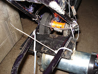
The motor is slung underneath the frame on this bike (would be within the triangle if there was room, but the belt I have is not long enough, and I don't want to buy a new one till I have to, as this one is perfectly good, just very short). The belt tension is adjusted via moving the motor forwards or backwards along the chainstay tubes--most likely I will first use radiator hose clamps thru slits cut in the base plate of the motor mount to clamp the motor to the tubes, though a better clamping solution is on the drawing board. The pulley/freewheel/sprocket device is mounted in the former rear-wheel dropouts of the front frame. The belt from the motor drives the pulley which drives the chain, and chain tension is adjusted via the axle's position in the dropouts.
I'll have to wait and see how well this performs once I get the mechanics built enough to do a test. I can use the dying SLAs for short tests on the road, and in-house stand tests can be done with the car batteries, probably for hours. (I ran the motor without load other than fan and pulley for more than half a day without making much of a dent in the battery voltage, drawing ~1.5A the entire time).
Search all of my sites with Google
Thursday, January 22, 2009
Motor Pulley to Freewheel and Sprockets device
Posted by
M.E.
at
1/22/2009 11:16:00 PM
![]()
Labels: Batteries, Bike parts, Desired Features, drivetrain, motor, Parts I need, Recumbent, salvage, steering, throttle
Subscribe to:
Post Comments (Atom)


No comments:
Post a Comment
Alternate suggestions or improvements to anything that's been posted is very welcome, and extreme detail is preferred to brevity.
Keep in mind that unless you leave an email address in your comment, I haven't any way to reply to you except to reply to your comment here. That means if you want a reply, you'll have to come back to *this* blog entry and it's comments to see my reply to you, unless you leave some method of contact within your comment.