Voting for the Instructables.com Light Up the Night Contest has started, so if you liked my CFL headlight and taillight idea, the actual instructable is here:
CFL-Headlight-and-Taillight-for-Electric-Bicycle
with a voting link near the top.
Monday, November 30, 2009
Voting on Instructables.com: CFL Headlight and Taillight Instructable
Sunday, November 29, 2009
Watt Meter Measurements, 30-35Wh/Mile
I finally got the chance to use one of those Turnigy Watt Meters to test some stuff on the CrazyBike, and it's nice enough, but I wish it measured current in reverse. It does allow reverse current flow with no problems, it just doesnt' register it. (I can charge the battery with it hooked up charger on motor plug of meter).
Now I know that my bike on a typical workday ~5-mile trip uses around 30Wh/mile on the 2.3 mile home-to-work trip, and about 35Wh/mile on the 2.5 mile work-to-home trip, loaded down with an additional 80-ish pounds of stuff in the cargo pods, including a 40-pound bag of dog food. I guess since it's hauling 300 pounds of bike and me, plus that stuff, it's not that bad.
This includes about two miles (one each way) at 17-18MPH, some of that into a stiffish headwind (10-15MPH) with at least 13 complete stops/starts for various intersections and traffic controls, and up to a bit over 19MPH peak speed here and there. Average on the PDA was about 12MPH, which includes longer-distance startups with the load in the pods on the way back.
Wh/mile wasn't nearly as good as I had expected based on analog panel meter readings and guesstimates. That panel meter is significantly low-reading, apparently, as I saw a bit more than half of the current readings on it as I do on this watt-meter.
For at least a very short time, there can be a peak of 105A battery side, driving the motor from stopped startup in a middle or high gear. That was on the way to work. In normal lower gears it's a peak of ~53A, on the way home from work, loaded up. That's using just the largest front ring (48T) and shifting between 6 rear rings from 28T up to 11T. The peaks must only a second at most, but that data isn't available from this meter--I'd need a Cycle Analyst and it's logging features to get that data.
Peak watts was 3281 on the way to work and 1784 on the way home.
Voltage dipped down to 31.11V on the way to work, and 39.11V on the way home. (No recharge between them, so must be caused by the high peak current drain at 105A.)
Total Ah usage was 1.905Ah on the way to work and 2.037Ah on the way home.
Oh, and as usual I run the lights all the time, day or night, which is another say, half an amp draw all the time, average, including the turn signal use. I don't currently have the lights wired in to the meter as I wanted to know only what the motor usage was first.
Thursday, November 26, 2009
Motor Rips Loose From Mounting Plate
(Much delayed posting due to holidaze and circumstances; was started thanksgiving night but not finished till the 28th)
Last week, on the way up toward Arrowhead along the canal, about 3 miles from home, the motor mounting plate gave way along the only rightside mounting bolt it had.
It looks much worse in person than I could capture on camera. The largest hole in it on the right rear of the plate is for the old motor's clutch lever to pass thru, and that weakened the plate enough in that area that the hole for the rightside mounting bolt of the new motor, right next to it and partly intersecting it, finally expanded and let the bolt pass thru it.
It took a small chunk of the plate out with it. This was during uphill travel on one of the under-road tunnels on the canal path; they're pretty steep. Not sure of the grade, but steeper than I can pedal up from a stop on my other unpowered bike, the DayGlo Avenger (the upright aluminum bike), without hurting my knees pretty badly even in the very lowest gear, and even that only at just enough speed to stay barely upright (if wobbly); perhaps 1-2MPH.
I didn't have any thicker steel plate, so I just cut another plate of the same material and same shape to weld to the existing one. First I had to hammer and bend the other plate back mostly flat, then I clamped them together, welded one edge (where it joins the frame), then clamped along the flat portion of the plates and welded thru the various holes in the plates (mounting screwholes from whatever they originally came off of) to the plate underneath, to join them more thoroughly. Not as good as a single thickness, most likely, but good enough for this, I hope. Sorry there aren't any pics of this process; again I didn't think to do it until too late.
After welding them, I did a lot of comparing, holding, marking, placing, and test-fitting of potential chainlines before I drilled any new holes, and before cutting the new slot for the chain to pass thru on the left edge of the plate (it's only major weak point now that there will not be slotted holes nor clutch lever hole).
Eventually I decided to do two things differently than before. First, to move the pedal crank chainring to the *right* side of it's spider, since it is a bolt-on to a flat plate.
This moves the pedal chainline right far enough to completely clear the motor chainline, even if I move the motor chainline more right as well. Then I did that, too, by flipping the hub over, cutting off more of the hub the same way I did it before (hacksaw while spinning it on lathe), and using the removed parts as spacers on the left.
This also allows me to center the motor better between the cranks, and it straightens the motor's chainline--part of the problem I had with it coming off (besides flex from the motor plate prior to failure) was that the chain had to be super-tight due to the chainline passing from left at front to nearly 1/4" out of line at rear, with no guide or jockey wheels to keep it lined up where it met the bottom of the receiver sprocket. So under the right circumstances (left turns with a lot of tilt, especially on bumpy roads or rough intersections, etc), it would come off, and sometimes tangle.
Now that won't happen, as the motor's chainline is as close to straight as I can see, as is the pedal chainline. The pedal chainline doesn't even need the tensioner/guide wheel anymore; even under bouncy conditions it stays on, so far, despite still being about 1/2 link too long.
I left the plate to bolt the wheel onto in case I have problems on the road; the wheel and bolt is in my toolkit.
While I was at it, I also welded up some battery retainer strips, just to give them some guide at the bottom, so I don't have to keep using the wood blocks (which deform over time and have to be readjusted) to keep the batteries from shifting around. For the front battery, I just used the bottom tray from a small standard computer UPS (the kind that uses a 7Ah battery), and cut a piece just long enough to tack weld onto the bike frame and still keep the bottom of the battery from moving side to side.
I cut a small slit for the hose clamp that secures the batteries to pass thru, for more clearance to the chain. No rubbing problems, even in a hard right turn. It does rub if the bike is tilted far enough to lift the rear wheel off the ground, using the right cargo pod as a "stand", but that's not relevant to riding it.
For the rear battery, which was the most problematic on the road, I took the two triangular strips left from cutting the new motor mount plate, and notched them to fit the frame and be out of the way of the motor bolts.
Then spot-welded to the frame and motor plate (as this also stiffens the motor plate some), and can now clamp the battery down without worries of it moving. Due to chain clearance, the clamp only goes around the rightside plate, but it is very secure and doesn't shift around even with that.
A quick shot of the PDA used as a bike computer, showing the readings at the time.
22MPH was unpowered gliding down into the tunnel that I had to walk the bike back out of due to the motor plate breakage. Usually (in daylight when I can see in the tunnel and it's entrances better) I can keep gliding until I am most of the way back up the other side, as long as there is no other traffic (normally there is not) or anyone sleeping in the tunnel with a cart full of their belongings (this happens more than encountering other traffic), and then I can engage the motor in a low gear and continue up the rest of the way.
This time it didn't work out like that, because when I engaged the motor, almost instantly the motor pulled out of the plate on the right side, which allowed it to be pulled left and back by chain tension, getting in the way of even the pedal chainline, which made me just stop right there, and set the parking brake lever (taken from the scooter) on the left, to the rear wheel. Then I saw what had happened, and just ended up walking the bike the rest of the way uphill, then walked it home via the surface paths.
Some new full-bike pics, including the headlight/taillight. First is the room light (same 15W/60W CFL that's in the HL/TL) and camera flash.
Next is just the room light, flash, and HL/TL.
Just the HL/TL
Just the room light, HL/TL. No flash.
Just the room light, no flash or HL/TL.
I've now gone another 31 miles, for 905 total, and the only thing I had to change (at 882 miles) was to weld the longer piece of hub that I'd cut off and used as a spacer, to the end of the hub it now sits against.
This is because the little pin that rests in the groove of both the hub and gearbox axle isn't long enough to totally fill the space from one to the other, and apparently can work it's way loose. The original one *was* long enough, but I managed to misplace it during my original modification of the hub, and had to make a new one; for whatever reason I no longer remember, I did not make it the same length. Now it's welded, *and* has a hardened torx-head bolt threaded into the groove for the rest of the length, to ensure full contact and power transfer between the axle and hub.
I was very lucky that it failed where it did, less than 1/4 mile from a friend with a welder and the large 19mm wrench it takes to undo that locknut, or I would not have made it home in any reasonable time that night--the motor couldn't transfer any torque to the drivetrain, and I could not have gotten the nut off to put the pin back in place (the washers block the pin from coming out, and thus anything I have from going in!). So my thanks to him for letting me barge in after turkey-day dinner and use his tools!
Tuesday, November 17, 2009
CFL Headlight and Taillight, Mounted and Wired In.
Something brought up by Fechter on Endless Sphere is that some CFLs are rated at one specific voltage and frequency, such as 110V 60hz.
Unfortunately if the CFL is one marked for a specific voltage and frequency, then they are not using a typical switching power supply front-end on it; they are probably using a linear power supply front-end. That means that yes, you could make it work, but you would have to rebuild the ballast inside.
Way cheaper and easier to just go get the other kind of CFL.
FWIW, I took a look around at the ones at various supermarkets and whatnot the last couple of grocery runs I made after starting this, and all of the ones I saw that had the bulb base visible and/or not in a non-openable package were listed as wide-range inputs, so they would probably all work. I haven't seen any of the other kind like you have in a while, but they're probably still being made.
There are also some that use an electronic ballast control chip, though I haven't seen inside them yet. Those chips have some sort of voltage protection in them, that might include UVLO; if so they probably won't work either.
Some new updates; I got the taillight "permanently" installed in place of the old taillight,

and mounted the cups/lens/CFL assembly as the headlight on the front stem in place of the old flat CCFL, but I couldn't find any of the metal cans and whatnot I thought I had and wanted to use for the CFL holder/reflector.
THe "redout" is because there's a white door less than two feet away from the taillight. :)
The lights are now run (as my old ones were) thru the headlight Hi/Lo switch on the lefthand control cluster from the Honda scooter (which also has the turn signals and horn button). Lo turns them off, Hi turns them on. Ground for the system is same as everything else, thru the breaker, so flipping that turns it all off, motor included.
I also managed to blow up the first CFL (the one wired straight to the cap) by somehow connecting it backwards to the power, even though I had tied a knot in the negative wire as always to be sure which way it went. :( It's just the transistors, and I probably have some I can use as replacements around here somewhere. Probably both NPN if like other schematics I've seen. So now I have that plain screw-in setup I was talking about, a little earlier than planned. :roll:
I let the setup run for a couple of hours after finishing the rewiring, and it ran fine the whole time. Just before turning it off, I tested with my "Extech" DMM that has a temperature probe, and got around 135F/60C inside the taillight housing. About 10F cooler inside the headlight housing, which doesn't make sense, since it has the WHOLE CFL inside it, instead of just the glass bulb, plus it's lined with the styrofoam cup and the plastic one outside that (and a bunch of tape).
On the headlight housing, I cut away part of the tape on either side to let light thru in a couple of little rectangles and taped on a pedal reflector on each side to give me amber side markers.

Cheap and cheesy, but it is now slightly more visible from the sides. It'll be better and more effective in the more final version once I find those cans, or make something out of sheet metal cut off something else.
CFL Headlight AND Taillight Test Ride and More Pics
Test rode it today, with the lights just taped and zip tied in place, using the new inverter setup (works a lot better than the celphone adapter, especially since it's getting colder out there; is already 48F and dropping, and the lights pulse some at startup, then smooth out and brighten noticeably as they warm up over the first 30 seconds to a minute.
In the driveway pics below, when the overheads are on, that's 4 four-foot 40W fluorescent tubes (bluish type), left on for a few minutes to warm up to full brightness (it's cold enough outside to make a difference to those, too, apparently). The bike is parked so the headlight is where the average car's rear bumper would end up if parked under the carport (didn't measure it). The front pics are taken while standing at the wall the bike is pointed at. The rear pics are taken from across the street on the sidewalk edge. The only other primary light source is the mercury-vapor streetlight on the T intersection a few dozen feet away.
This new taillight is WAY better than my 8-LumiLED taillight, even including the other 8 LumiLEDs that are side-markers on each end of it reflecting off the back of the cargo pods.


Oh, and the taillight is just connected thru the screwbase--I didn't bother opening it up to bypass the diodes, since the input voltage is now so much higher. I'll probably take the bypass off the headlight, too, so I can just make a screwbase mount and be able to replace the light any time with any regular CFL. Then I can more easily try different wattage versions and brands (and colors) to see what happens with each one.
The headlight is much better than my old front headlight, even if it looks like it's made from crap in daylight, it looks great at night. :)
Needs a better beam, though; it has too much of the light being scattered close to the bike, and not enough cast far ahead. Still far better than I had before, but not good enough for a poorly-lit road or canal path at full speed (20MPH). The lens helps some, just not enough. I think I will work on some parabola style reflectors to put around the base of the CFL in front of the ballast section, and work from there to improve the concentration of more light in the center, while still letting it get a lot of diffuse spillover for side-lighting and visibility.

I'm also going to take some amber pedal reflectors and put them in slots on the sides of the light tube to give me front and side markers. :)
The taillight will go below the brake light bar, where the existing taillight is now. At the moment it's just ziptied above the bar.
Oh, and that helmet light comparison:

Monday, November 16, 2009
CFL Taillight
I looked for my light meter as long as I could today, but never found it. I wanted to do before/after comparison testing in lumens with the lens and without, and with whatever new reflector I come up with. I guess I'll try it when I do run across the thing.
I did find a few of my higher voltage inverters, for laptops. A few Apple Powerbook 24V adapters, which are isolated but won't start on even 40V. Neither would two of the 19V generic adapters (one Targus and one no-name), but the lightest and smallest, an Averatec, did, and kept running down to at least 30V, where I stopped worrying. :) At least *something* from Averatec is actually useful. :P
The 24V Apples are lighter than the typical 19V laptop adapters I have, although the Averatec is lighter than all but one of the Apples. All the 19V will do around 3A, while the 24V will only do 1.25A; this doesnt' matter for this application unless I need to run more than 6 or 7 of these. ;) I think two ought to do it--one rear and one front. I might go for two on each end for redundancy, though.
I also found a little plastic box that will be perfect for the rear end. I don't know what it used to be, but it's ABS and about 3/16" thick walls. Black plastic, so will enclose light very well. I can just take white plastic drink cups and cut them up for the inside diffuser/reflectors, to line the box with to make most of the light go out. Then secure red bike reflectors (minus their backings) to the open areas to the rear. Cut some holes on the ends, and put more red reflectors there, for side markers. One light in the center ought to be plenty, but one on each end would be even better.
Still pondering for the front canister.
I made a temporary taillight out of the old Honda scooter's taillight casing, which is cracking from age and abuse. It'll last long enough to give me time to build the other one above.
Had to remove the incandescent mounting fixture and reflector (you'll see where I painted it white inside instead of black to help reflect more light out of it with the incandescent, during early tests with CrazyBike2's lighting, until I gave up on it due to too much power wasted on the incandescent).

Then I had to drill out the hole large enough for the base of the CFL to fit thru. So out comes MEGA DRILL, a very old B&D drill (still has a ground plug!) with a completely metal case (rescued by a friend from a trashcan especially for me), with a reduction-gearing hand-gripped drill extension to allow me to use the much larger-shafted Unibit for panel holes.

And a test-fit:

Then I setup a test rig to determine which of those AC adapters would work, using three identical batteries to what is on m bike, with about 3/4 charge on them. A back plate off the UPS they came from, holding all the AC outlets, is held between the third battery and the other two, and one outlet pair is wired across the pack, so I can just plug in adapters and meter their outputs.
Then I wired up the Averatec 19V adapter (which is isolated) so it's plugged into the pack for it's voltage input, with it's negative output wired to pack positive, and it's positive output wired to the screw base of the CFL. The tip of the CFL base is wired to the negative of the pack, with the Fluke measuring across pack plus Averatec, at 53.8/9VDC.
The pic above is with the camera flash on by accident. Below is no flash, with room lighting of 2x 40W 4-foot fluorescent tubes overhead at cieling height.
Then a pic of it with lights off, camera in auto mode no flash (ISO320)
and a pic of the wall facing it, about 5 or 6 feet away.(ISO320)
Then some manual-setting pics, first at ISO1000 (exp 1/5 sec) then at ISO80 (exp 1/60 sec):


then with the room lights back on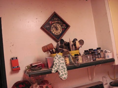

Then some other lighting comparisons, such as a CFL on battery at 56VDC compared to an identical CFL on 115VAC. Room lights off, ISO1000, F/7.1, 1/2000sec:
Same camera settings, both taillight and the battery CFL in parallel on pack/Averatec:

Then a 12V 43W halogen I found when looking for edison-base screw in sockets for testing:

It sucks 3.25A constantly at 12.1V (current battery state) for that light, which is not a lot more than a single CFL puts out, but is mostly focused in one direction. Roughly 40W of power. It also gets too hot to touch in a fairly quick time.
The CFL does not get hot (just warm), but heat still ages parts, and will probably affect this, too. It only draws 380mA for BOTH the CFLs together, INCLUDING the inverter power of 100mA, for a total of 3.8W + 16.5W = 20.32W, for even more light output than the halogen, and little heat.
Oh, and this is basically what my old CCFL headlight looks like inside:
Subscribe to:
Posts (Atom)